
Sheet metal drawings for fabrication
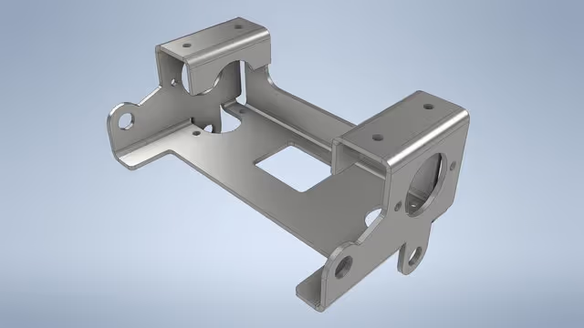
In the world of precision manufacturing, the transition from a conceptual design to a physical metal component is a journey of mathematical accuracy. Whether it is a simple bracket or a complex medical instrument enclosure, the quality of the final product depends entirely on the quality of the technical drawings.
Preparing sheet metal drawings for fabrication is more than just sketching a part; it is about providing a “road map” that accounts for material thickness, machine limitations, and the physics of bending metal. Here is a comprehensive look at the professional workflow used to transform a 3D concept into a fabrication-ready 2D blueprint.
1. The Foundation: 3D Modeling and Material Selection
The process almost always begins with a 3D CAD (Computer-Aided Design) model. Unlike solid machining, sheet metal design requires the designer to select a specific material thickness from the outset.
Because sheet metal is manufactured in standard gauges, the drawing must reflect real-world availability. During this stage, engineers must account for the K-Factor—a ratio that represents the location of the neutral axis relative to the thickness of the material. This is critical because when metal is bent, the inner surface compresses and the outer surface stretches. The neutral axis is the “sweet spot” that remains constant in length.
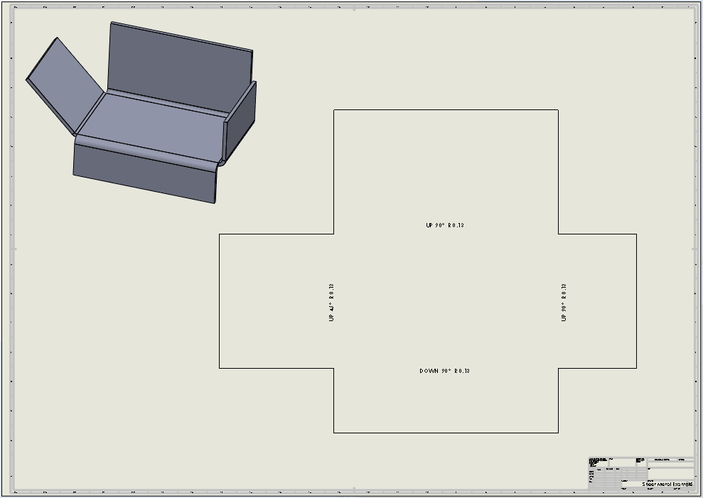
2. Developing the Flat Pattern
The most vital component of a sheet metal drawing package is the Flat Pattern. This is a 2D representation of the part as it looks before any bending occurs.
To create an accurate flat pattern, designers use Bend Allowance and Bend Deduction calculations. If these calculations are off by even a fraction of a millimeter, the final dimensions of the folded part will be incorrect, leading to assembly issues or wasted material. Modern CAD software automates much of this, but the drafter must manually verify that the software’s “unfolding” logic matches the specific tooling used by the fabricator.
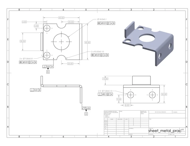
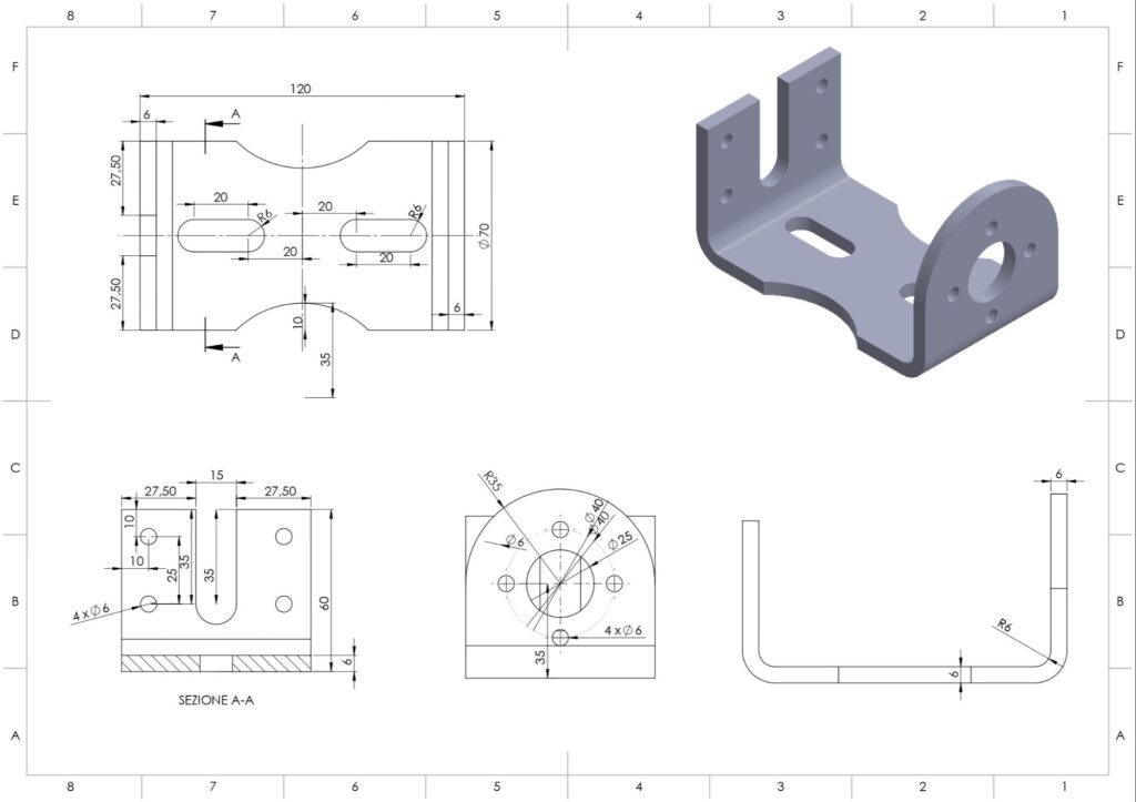
3. Implementing GD&T and Tolerances
A drawing without tolerances is just a picture. Geometric Dimensioning and Tolerancing (GD&T) is the universal language used to tell the fabricator exactly how much deviation is acceptable.
For sheet metal, key tolerances usually include:
Linear Dimensions: The overall length and width.
Hole Diameters: Ensuring fasteners will fit correctly.
Bending Angles: Typically held to ±1°or ±0.5° depending on the application.
Flatness: Ensuring the base material hasn’t warped during laser cutting or punching.
4. Defining Bend Lines and Tooling Notes
On the technical drawing, bend lines are typically represented by centerline phantoms. Each bend must be clearly labeled with:
Bend Direction: (Up or Down)
Bend Angle: (e.g., 90°)
Inside Bend Radius: This must be achievable with the fabricator’s available “V-dies” and punches. If a designer specifies a radius that is too small, the metal may crack; if it is too large, the part may lose structural integrity.
5. Hardware and Secondary Operations
Sheet metal parts rarely exist in isolation. They often require “PEM” fasteners, standoffs, or threaded inserts. The drawing must specify the exact part number for this hardware and the precise hole size required for a “press-fit” installation.
Additionally, any secondary operations—such as powder coating, anodizing, or silk-screening—must be noted. Designers must indicate if dimensions apply before or after plating, as a thick powder coat can change the diameter of a precision hole.
6. Exporting for Production (DXF and PDF)
Once the drawing is polished, it is exported into two primary formats:
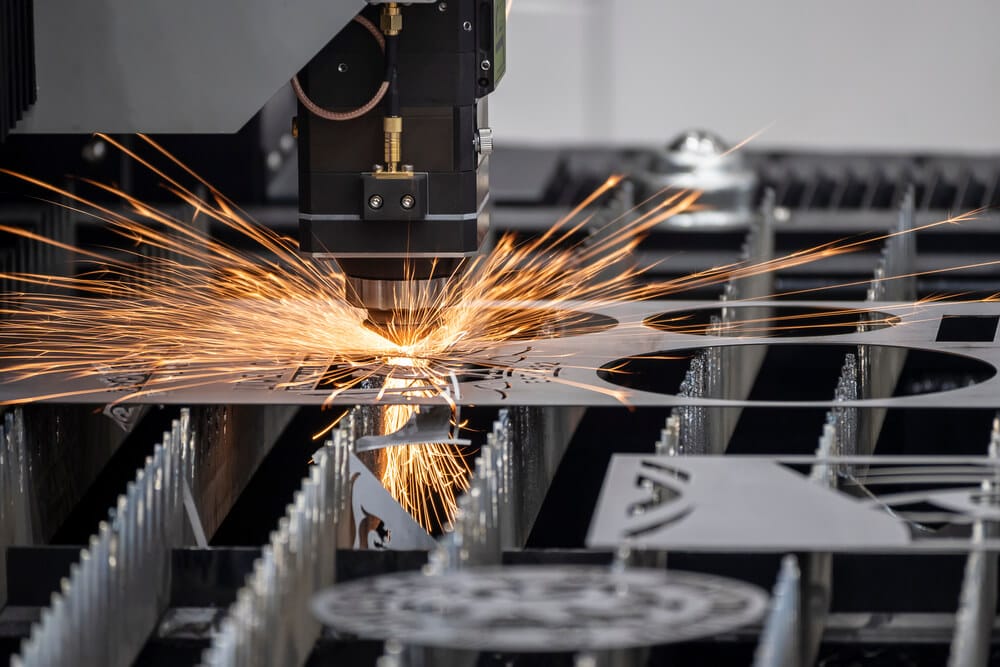
DXF/DWG Files: These “vector” files are fed directly into CNC laser, waterjet, or plasma cutting machines. They contain the geometry of the flat pattern without the borders or text.
PDF Drawings: These serve as the “legal” document. They include the title block, material specs, tolerances, and 3D isometric views to help the shop floor technicians visualize the finished product.
Conclusion: Quality Drawings Save Costs
In sheet metal fabrication, “measure twice, cut once” starts at the computer screen. A well-prepared drawing reduces “shop floor questions,” eliminates scrap metal waste, and ensures that the first prototype fits perfectly into the final assembly. By following these rigorous steps—from K-Factor calculation to GD&T implementation—designers bridge the gap between a digital idea and a durable metal reality.