
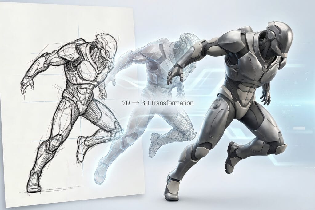
How to convert hand sketch into CAD drawings
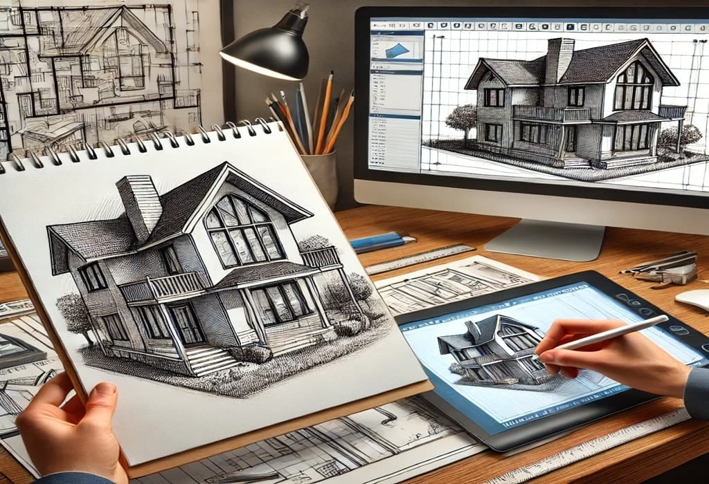
In the fast-paced world of modern manufacturing and construction, the “napkin sketch” remains the birthplace of innovation. However, a hand-drawn concept is only the first step. To bring an idea to life—whether through 3D printing, CNC machining, or structural assembly—that sketch must be converted into a precise CAD (Computer-Aided Design) drawing.
Converting a hand sketch into CAD is more than just tracing lines; it is a process of “digital engineering” where rough proportions are replaced by mathematical certainty. Here is the professional workflow for turning manual sketches into high-quality CAD files.
1. Preparation: Clean Up the Manual Sketch
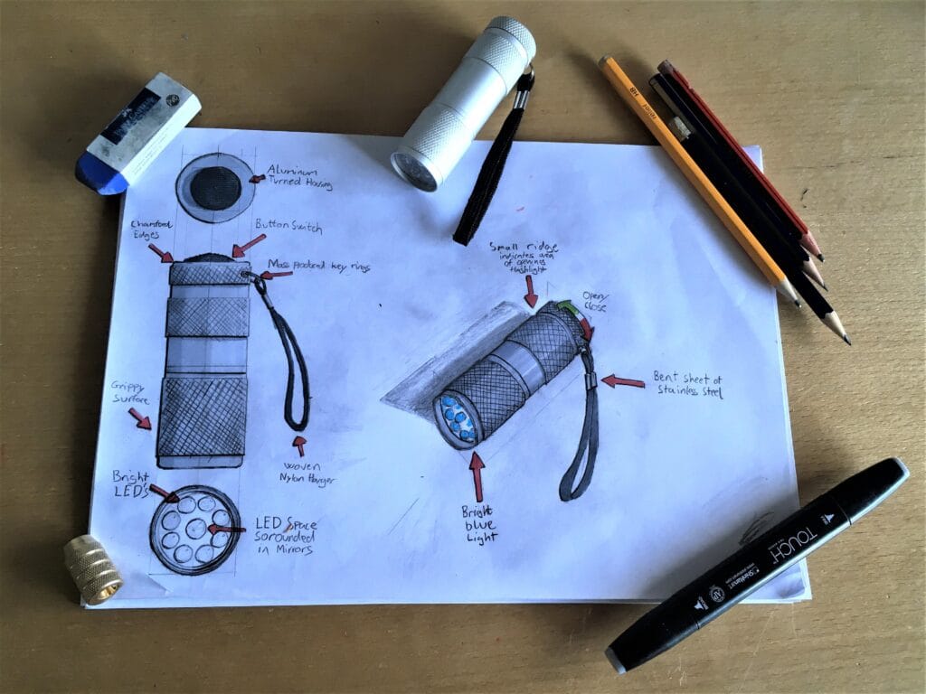
The accuracy of your digital output is heavily dependent on the quality of your input. Before moving to the computer, ensure the hand sketch is as clear as possible.
Define Key Dimensions: Even if the sketch isn’t to scale, write down the critical measurements (length, width, hole diameters).
Use High Contrast: If the sketch is in light pencil, go over the primary outlines with a fine-liner pen. This helps both the human eye and automated “raster-to-vector” software identify the geometry.
Capture the Image: Use a high-resolution scanner if possible. If you are using a smartphone, ensure you are shooting directly from above (parallel to the paper) to avoid perspective distortion, which can warp dimensions.
2. Importing and Scaling the Image
Once you have a digital file (JPEG, PNG, or TIFF), import it into your CAD environment (such as AutoCAD, SolidWorks, or Fusion 360).
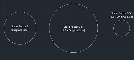
The most critical sub-step here is Scaling. Since the image doesn’t have native units, you must use a “Reference Scale.” Find a known dimension on your sketch (e.g., a line labeled 100mm), draw a CAD line of exactly 100mm next to it, and then use the Scale command to match the image size to your digital line. Without proper scaling, the CAD drawing is just an illustration, not a technical document.
3. The Layering Strategy
Professional CAD drafting relies on organization. Before drawing a single line, set up your layers. This allows you to toggle the visibility of the original sketch and keep the workspace clean.
Layer 0 (Background): Your original scanned sketch. Set the transparency to 50% so you can see your CAD lines clearly over it.
Layer 1 (Geometry): The actual outlines of the part.
Layer 2 (Dimensions): The technical annotations.
Layer 3 (Centerlines/Hidden Lines): For internal features and symmetry.
4. Drafting: From Raster to Vector
Now comes the “conversion” phase. You have two choices: Manual Tracing or Automated Conversion.
Manual Tracing (Recommended for Precision)
For mechanical parts or architectural floor plans, manual tracing is superior. Use the sketch as a guide, but rely on the numerical inputs for accuracy. Instead of clicking where the sketch shows a corner, type the exact coordinate or length. This ensures that a line that looks straight in the sketch is perfectly horizontal in the CAD file.
Automated Vectorization (Best for Artistic Shapes)
Tools like Adobe Illustrator or specialized CAD “Raster-to-Vector” plugins can automatically trace lines. While fast, this often creates “splines” (curved lines) that are difficult to edit or dimension later. Use this method for logos or organic shapes, but avoid it for parts requiring tight tolerances.
5. Applying Constraints and GD&T
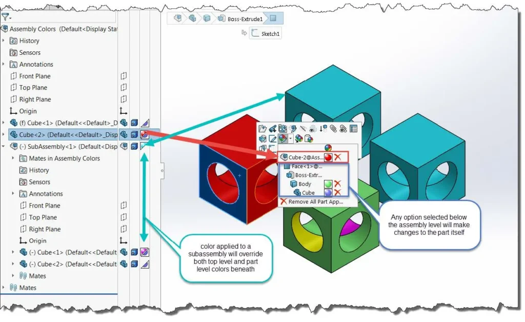
Once the basic lines are drawn, it is time to apply the “intelligence” of CAD. In parametric software (like SolidWorks), you apply Constraints (e.g., Parallel, Perpendicular, Tangent).
If your hand sketch shows a circle touching a line, you must apply a Tangent Constraint in CAD to ensure the transition is mathematically smooth. This is also where you implement GD&T (Geometric Dimensioning and Tolerancing) to define the allowable limits for manufacturing.
6. Verification and 3D Modeling
If the goal is a 3D part, the 2D CAD profile is “Extruded” or “Revolved” to create volume. This is the ultimate test of your conversion: if the 2D lines aren’t perfectly joined (a “closed loop”), the 3D model will fail.
Always perform a “Final Check” by overlaying the finished CAD drawing on the original sketch. The CAD version should look like a “perfected” version of the hand-drawn original—cleaner, sharper, and ready for the factory floor.
Conclusion: Why Accuracy Matters
Converting a hand sketch to CAD is the bridge between a dream and a physical product. A professional conversion ensures that your design is ready for CNC programming, 3D printing, or patent filing. While DIY software exists, hiring a professional drafting service ensures that your digital files are optimized for DFM (Design for Manufacturing), saving you from costly errors during production.